How Can We Help?
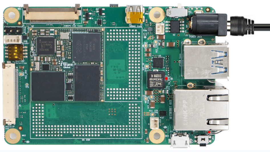
Get started with i.MX 91 Pico ITX Single Board Computer


MINICOM TUTORIAL
TERA TERM TUTORIAL
PUTTY TUTORIAL
MINICOM TUTORIAL
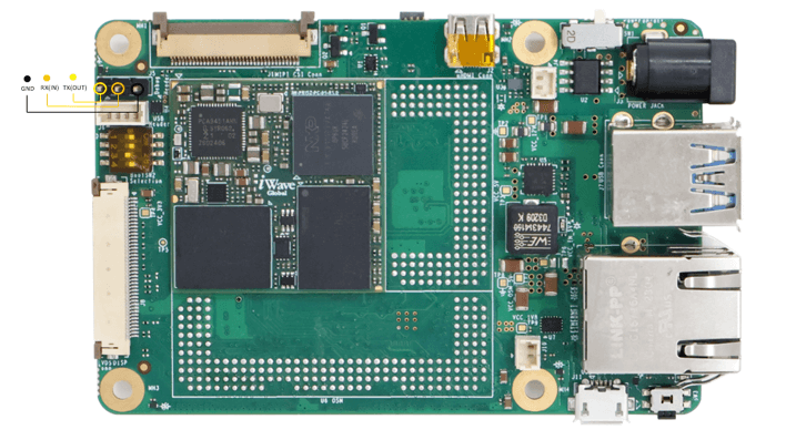
- On the command prompt of the Linux host machine, run the following command to determine the port number:
$ ls /dev/ttyUSB* - The smaller number is for Arm® Cortex®-A53 core and the bigger number is for Arm® Cortex ®-M4 core.
Minicom
Use the following commands to install and run the serial communication program (minicom as an example):
- Install Minicom using Ubuntu package manager.
$ sudo apt-get install minicom - Launch Minicom using a console window using the port number determined earlier.
$ sudo minicom -s - Configure Minicom as show in below figure

- Next step is to Power ON the board.
TERA TERM TUTORIAL
Install the driver for Debug USB Port in Host PC/Laptop using the below link.
http://ftdichip.com/drivers/vcp-drivers/
- Download Tera Term. After the download, run the installer and then return to this webpage to continue.
- Launch TeraTerm. The first time it launches, it shows the following dialog. Select the serial option. Assuming your board is plugged in, there should be a COM port automatically populated in the list.

- Configure the Serial Port Settings.
Go to Setup Serial Port and change the settings as shown below.

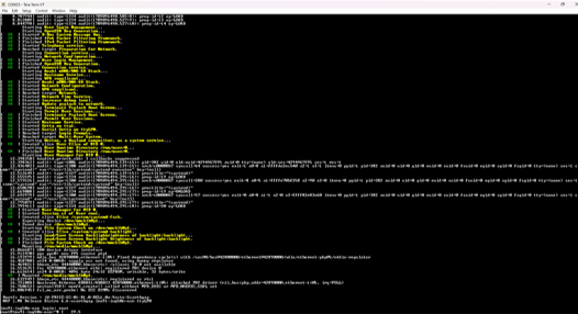
- Verify that the connection is open. If connected, Tera Term shows something like below in its title bar.

- Next step is to Power ON the board.
PUTTY TUTORIAL
Install the driver for Debug USB Port in Host PC/Laptop using the below link.
http://ftdichip.com/drivers/vcp-drivers/
- Download PuTTY. After the download, run the installer and then return to this webpage to continue.
- Launch PuTTY by either double clicking on the executable file you downloaded or from the Start menu, depending on the type of download you selected.
- Configure In the window that launches. Select the Serial radio button and ether the COM port number that you determined earlier. Also enter the baud rate, 115200

- Click Open to open the serial connection. Assuming the board is connected and you entered the correct COM port, the terminal window opens. If the configuration is not correct, puTTY alerts you.
- Next step is to Power ON the board.