Get started with Zynq UltraScale+ MPSoC ZU15/ZU9/ZU6 SOM Development Platform
開梱
Remove the Development Platform from box and place above the ESD free area. Use anti-static pad/mat with proper grounding to place the Development Platform. Also make sure that, below deliverables are received without any physical damage.
Development kit contains:
- Zynq UltraScale+ MPSoC (ZU15/ZU9/ZU6) SOM Development Platform
- 12V、5A電源
- 安全ガイドライン
- USBデバッグケーブル
- Fan Sink
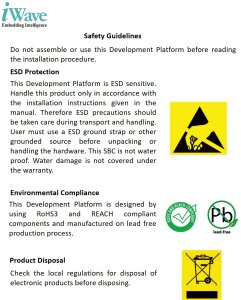

安全ガイドライン
Zynq UltraScale+ MPSoC (ZU15/ZU9/ZU6) SOM Development Platform


USBデバッグケーブル
12V、5A電源
知る

Zynq UltraScale+ MPSoC (ZU15/ZU9/ZU6) SOM – Top view
1. Zynq UltraScale+ MPSoC
2. Boot Mode Switch
3. PMIC Programming Header
4. 5V Fan connector
5. JTAG Header
 SOM Bottom view")
Zynq UltraScale+ MPSoC (ZU15/ZU9/ZU6) SOM– Bottom view
6. Board to Board connector 1
7. Board to Board connector 2
 SOM Development Platform – Top view")
Zynq UltraScale+ MPSoC (ZU15/ZU9/ZU6) SOM Development Platform – Top view
1. PMOD Connector 2
2. Board to Board Conn 1
3. PMOD Connector 1
4. JTAG Header
5. Board to Board Conn 2
6. PS IO Header
7. RESET Switch
8. ON/OFF Switch
9. Power Jack
10. Debug UART Connector
11. USB OTG Connector
12. GEM0 Ethernet Jack
13. GEM3 Ethernet Jack
14. Display Port
15. PS GTR Config Switch
16. SFP+ Connector
17. PCIe X1 Connector
18. SDI IN HD BNC Jack
19. SDI OUT HD BNC Jack
20. Standard SD Connector
21. USB Type C Connector
22. FMC Connector 1
23. CAN Header
24. FMC Voltage Select Switch
25. FMC Connector 2
 SOM Development Platform– Bottom view")
Zynq UltraScale+ MPSoC (ZU15/ZU9/ZU6) SOM Development Platform– Bottom view
26. RTC Battery Holder
27. M.2 SATA Connector
Download FTP Contents
All the technical resources of iW-RainboW-G65D Zynq Ultrascale+ MPSoC (ZU15/ZU9/ZU6) SOM Development platform is available in iWave FTP server.
FTP Folder structure

For FTP Credentials, Contact : mktg@iwave-global.com
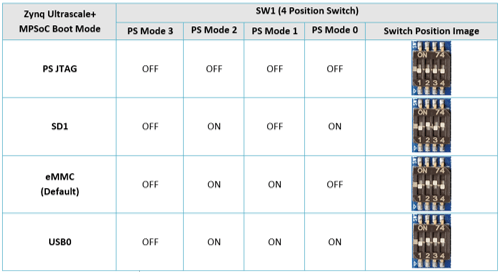
ブートスイッチ設定
Make sure On-Board Switch (SW1) is set properly according to the boot mode selection.

SW1-Boot Switch selection
デバッグポートの設定
Connect the 12V power supply plug to the power connector (J4) of the Development platform as shown below and Switch ON(SW2) the power supply

Install the driver for Debug Port in Host PC/Laptop using the below link
https://ftdichip.com/products/ft232rq/
Connect TypeA end of USB cable to PC and MicroB end of USB cable to Development platform’s Debug USB MicroAB Connector (J5) as shown below. iW-RainboW-G65D Debug Port Setting Setup the Debug Terminal parameters.
Baud Rate : 115200
Data bits : 8
Parity : None
Stop Bits : 1
Flow Control : None
JTAG接続
iW-RainboW-G65D Zynq Ultrascale+ MPSoC (ZU15/ZU9/ZU6) SOM Development platform Support JTAG interface in SOM and Carrier Board for MPSoC/FPGA Programming and debugging.
Example JTAG Cable which is tested with this Platform is mentioned below.
JTAG-HS2 Programming Cable
Part Number: 410-249
JTAG Connection to SOM

JTAG Connection to Carrier Board

電源オン
Connect the 12V power supply plug to the power connector (J4) of the Development platform as shown below and Switch ON(SW2) to power
Once power is applied to the Development platform, the power LEDs in Zynq UltraScale+ MPSoC(ZU15/ZU9/ZU6) SOM and Carrier Board will glow as shown in the below image.

- Power connector
- SW2(Power Switch)
3. Carrier Power LED
4. SOM Power LED
警告だ:
- Do not try to connect any other Power Supply other than supplied along with Zynq UltraScale+ MPSoC(ZU15/ZU9/ZU6) SOM Development Platform.
- Do not plug or remove the Zynq UltraScale+ MPSoC(ZU15/ZU9/ZU6) SOM from carrier board with live power.
- 電源LEDが点灯しない場合は、iWaveにご連絡ください。
テスト環境のセットアップ
Once power is applied to the Development Platform as explained in the previous section, boot messages being displayed in the debug terminal of the PC/Laptop which is connected to the Development platform. Press any key in terminal immediately to see the command prompt of the Boot loader or wait until OS boots.
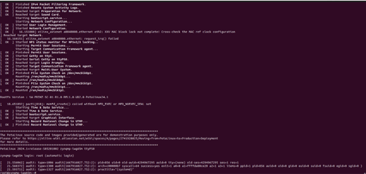
コマンドプロンプト(Linux)

Command Prompt (Uboot)
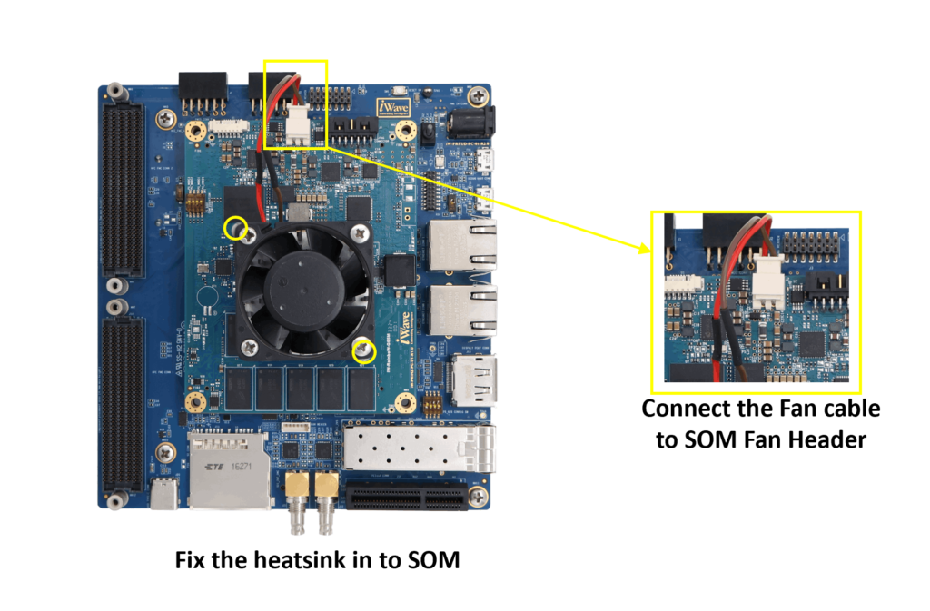
ヒートシンクの統合
iW-RainboW-G65D Zynq Ultrascale+ MPSoC (ZU15/ZU9/ZU6) SOM Development platform comes with Heatsink + Fan attached to it. Make sure to power up the platform only with Heatsink + Fan attached.
Below is the Heatsink + Fan integration procedure for reference.
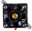
ヒートシンク+ファン
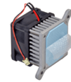
Peel off Thermal Pad Sticker